Nuclear Instruments and Methods in Physics Research A 535 (2004) 139–142
Design and status of IceCube
Martin Kestel
1
104 Davey Lab, PMB 29, State College, Penn State University, University Park, PA 16802, USA
For the IceCube collaboration
Available online 12 August 2004
Abstract
IceCube is a kilometer-scale high-energy neutrino detector that builds on the wealth of experience accumulated with
its smaller predecessor, AMANDA. An international collaboration has begun construction of key components of the
IceCube detector and deployment operations at the South Pole will begin in late 2004.
The underlying design of the IceCube detector and of the DAQ system are presented here, emphasizing
the digital optical modules (DOMs) as the smallest discrete IceCube building block. The event reconstruction
critically relies on a relative timing accuracy from DOM to DOM of a few nanoseconds over inter-DOM separations of
up to 1 km.
r
2004 Elsevier B.V. All rights reserved.
1. Physics goals
Through the detection of very high-energy
neutrinos (threshold a few 100 GeV), IceCube
[2,3] will open a new window on the universe. By
viewing astronomical sources with neutrinos as
astronomical messengers, it will address funda-
mental questions in high-energy astrophysics,
particle physics and cosmology. Through the
detection of surface electrons and muons, the
associated IceTop surface array will allow us to
study the chemical composition of high-energy
cosmic rays
ð
E
?
10
18
eV
Þ
and will also help
calibrate IceCube and provide a background
veto. IceCube and underwater neutrino telescopes
[4]
share scientific interests, such as searches
for steady or variable neutrino emission from
point-like source candidates like active galactic
nuclei (AGN), supernova remnants (SNR),
microquasars and gamma ray bursts (GRB). By
virtue of the low ambient noise level in the ice,
the ability to detect low-energy supernova neu-
trinos as an increase in the overall trigger rate is
unique to IceCube among all UHE neutrino
detectors. On the more speculative side, searches
for neutrinos from annihiliations of weakly inter-
acting massive particles (WIMPs), for magnetic
monopoles and other exotic particles like strange
quark matter or SUSY Q-balls can be listed (see
e.g. Refs. [5,6]).
ARTICLE IN PRESS
www.elsevier.com/locate/nima
0168-9002/$ - see front matter
r
2004 Elsevier B.V. All rights reserved.
doi:10.1016/j.nima.2004.07.119
Email address:
mka@phys.psu.edu (M. Kestel).
1
See
[1]
for a full author list.
2. Detector design and status
IceCube will consist of 4800 digital optical
modules (DOMs), organized in 80 strings, each
with 60 DOMs attached, buried in the ice at depths
of 1450–2450 m. DOMs will have a vertical
spacing of 17 m and the strings will be regularly
spaced horizontally by 125 m. At each string
location two IceTop tanks, each containing two
DOMs frozen in ice, will be deployed. The buried
DOMs will have an effective surface area of
around 1 km
2
;
promising optimal sensitivity for
neutrinos in the energy range of 1–10 000 TeV
while being able to trigger on all higher- and on
some of the lower-energy neutrinos, including
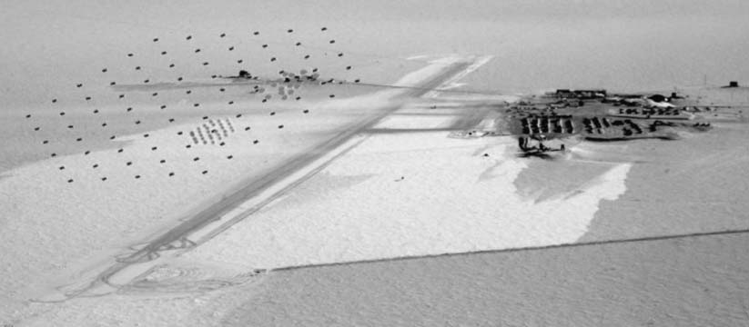
MeV bursts [8]. The positions of IceCube strings,
and the IceTop tanks deployed above them, are
shown in
Fig. 1. Simulations have shown that
IceCube’s sensitivity to possible signals is roughly
constant for a wide range of feasible configura-
tions.
DOMs form the fundamental building blocks of
the IceCube detector. Each DOM contains a 10
00
Hamamatsu R-7081 photo multiplier (PMT). The
high voltage for the PMT is converted in the DOM
from its 48 V DC power supply to achieve the
design gain of around 5
?
10
7
:
Within a DOM, the
PMT signal is split into two copies, with one used
for triggering and the other delayed and then
digitized if the threshold condition is met. Digiti-
zation occurs in two types of DOM-resident
digitizers, to extend the digitization time while
keeping the resolution high at early times. There is
a set of two four-channel ASIC analog transient
waveform digitizers (ATWDs) and a commercial
40 MHz FADC with up to 256 samples and 16-bit
resolution available. The two ATWDs operate at
300 MHz and at none, 16, 32, 64 or 128 sample
depths with 8- or 16-bit resolution. The two
ATWDs are fed signals in a ping-pong manner,
reducing DOM dead time to less than 1%. The
first three channels of each of the ATWDs are fed
signals that have been amplified with factors of 16,
4 and 2/3. This combination of ATWDs and
FADC ensures the design dynamic range of up to
200 photo electrons (p.e.) within the first 15 ns and
up to 2000 p.e. within the first 5
m
s
:
The fourth
ATWDchannel can be connected to various
inputs like the DOM-clock ticks or LED driving
currents, creating a versatile diagnosis and cali-
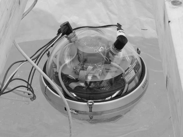
bration tool. The DOMs further contain a 405 nm
LEDflasher board, producing programmable light
flashes of various intensities detectable by other
modules in the array. This capability is useful for
studying ice properties and calibrating the relative
positions of DOMs. A preliminary version of a
DOM, deployed in an IceTop tank in January
2004, is shown in Fig. 2.
The DOM mainboard has a free-running timer
which needs to be synchronized with nanosecond
accuracy to GPS time, requiring re-calibration
roughly every minute. As shown in
Fig. 3,a
surface circuit sends a bipolar signal at a GPS-
latched time
t
1
;
received at a time
t
2
:
After a
certain, fixed time interval
d
t
;
an identical circuit in
the DOM sends an identical bipolar pulse to the
ARTICLE IN PRESS
Fig. 1. Aerial view of South Pole and positions of the IceTop tanks resp. the IceCube strings (black), Spase-2 stations (grey, dense,
regular foreground pattern
[7]) and the AMANDA strings (larger grey pattern). Courtesy V. Papitashvili.
M. Kestel / Nuclear Instruments and Methods in Physics Research A 535 (2004) 139–142
140
surface, detected at a time
t
4
:
The cable transmis-
sion time is then:
t
Down
¼
t
Up
¼ð
t
4
?
t
1
?
d
t
Þ
=
2
:
This calibration reduces signal time spread to the
inevitable contribution from light scattering in the
Antarctic ice.
Currently a fully digital, TCP/IP-based ap-
proach for the DAQ system is under development,
following closely the modular structure of the
experimental setup: each
String Processor
stores
DOM-data and passes trigger primitives on to the
InIce Trigger
, which, after examining trigger
primitives from all
String Processors
, sends its
trigger decisions to the
Global Trigger
. The
Global
Trigger
combines
InIce Trigger
,
IceTop Trigger
and other (external) information to form its
decision. If positive, the
Event Builder
is instructed
to retrieve DOM data from the
String Processors
and assembles them to IceCube events that get
passed to the
Online Filter Cluster
for further
processing. All of these DAQ system elements are
implemented in commercial computers.
The drilling process has been improved in
several aspects compared with the AMANDA
procedure: setup time for a season will be only 3–5
weeks; 60 cm diameter holes will be drilled with
water of 90
1
C from a number of heaters with a
total power of 5 MW (vs. 2 MW for AMANDA), a
larger hose diameter will reduce drill time to 40 h,
and the fuel consumption will be lowered by about
30%. With an estimated string drop time of
around 20 h, it should be possible to deploy 16
or more strings per austral summer season, leading
to a construction time of 5–6 years for the entire
detector.
3. Summary
With the assembly and testing of the first batch
of DOMs under way, the IceCube collaboration is
on track for deployment of the first set of strings at
the end of 2004. The digital approach to readout
and triggering, together with the sophisticated
time calibration, will help to overcome the
challenges posed by the sheer size of the detector
and the time spreads induced by the Antarctic ice
as a detector medium, enabling IceCube to
produce useful data for scientific purposes just
after the first few deployments.
Acknowledgements
This research was supported by the following
agencies: National Science Foundation—Office of
Polar Programs, National Science Foundation—
Physics Division, University of Wisconsin Alumni
Research Foundation, USA; Swedish Research
Council, Swedish Polar Research Secretariat,
Knut and Alice Wallenberg Foundation, Sweden;
German Ministry for Education and Research,
Deutsche Forschungsgemeinschaft (DFG), Ger-
many; Fund for Scientific Research (FNRS-
FWO), Flanders Institute to encourage scientific
and technological research in industry (IWT),
ARTICLE IN PRESS
Fig. 2. The first DOM frozen into a prototype IceTop tank at
South Pole (January 2004). Photo by John Kelley/NSF.
t
1
t
4
t
2
t
3
DOM Time
DOM
sends
DOM
receives
t
δ
GPS Time
Surface receives
Surface
sends
up
T
down
T fixed interval
Fig. 3. DOM time calibration, see text.
M. Kestel / Nuclear Instruments and Methods in Physics Research A 535 (2004) 139–142
141
Belgian Federal Office for Scientific, Technical and
Cultural affairs (OSTC), Belgium; Inamori Science
Foundation, Japan; FPVI, Venezuela; The Nether-
lands Organization for Scientific Research
(NWO).
References
[1] J.A. Ahrens, et al., Astroparticle Phys. 20 (2004) 507.
[2] IceCube Homepage, http://icecube.wisc.edu.
[3] S. Yoshida, for the IceCube Collaboration, Proceedings of
the 28th ICRC, 2003, p. 1369.
[4] Antares,
http://antares.in2p3.fr/; Baikal,
http://www-
zeuthen.desy.de/baikal/baikalhome.html; Nemo,
http://ne-
moweb.lns.infn.it/ Nestor, http://www.nestor.org.gr/.
[5] C. Spiering, for the Amanda collaboration, Proceedings of
the 27th ICRC, 2001, p. 1242.
[6] F. Halzen, astro-ph/0311004.
[7]
http://ast.leeds.ac.uk/haverah/spase2.shtml.
[8] M. Leuthold, Proceedings of the Workshop on Large
Neutrino Telescopes, Zeuthen, 1998,
http://www.ifh.de/
nuastro/publications/conferences/proc.shtml.
ARTICLE IN PRESS
M. Kestel / Nuclear Instruments and Methods in Physics Research A 535 (2004) 139–142
142
Back to top