1
R&D working group report
SAC May 2009
Klaus Helbing, Wuppertal & Hagar Landsman, Madison
●
Goals and tasks
●
Working group structure
●
Status of R&D
refraction, attenuation, background
–
Acoustics
–
air shower radio
–
in-ice radio
●
Conclusions for design of extension
●
Road forward
2
Common goals
●
Most general:
–
Extend IceCube and use unique facility and
environment/infrastructure at SP:
Only place to combine optical & radio &
acoustics & air showers
i.e. imitate the IceTop – InIce relation
●
Primary motivation:
–
GZK neutrinos
–
Expand acceptance of IceCube for EeV neutrinos
by orders of magnitude
●
Also:
–
determine EHE neutrino cross section
–
air shower physics (inclined, composition, EHE)
3
Tasks of R&D working group
●
work out task distribution amongst
participating institutions
●
establish Letter Of Intent (LOI)
●
define interfaces and common infrastructure
for different sensors (in/on ice, methods, ...)
●
establish milestones for an intermediate
scale detector (~ 5 GZK-
ν
's/year)
●
establish a road map towards a full scale
detector (~ 50 GZK-
ν
's/year; O(1000) km
2
)
●
coordinated planning of funding proposals
4
Structure of R&D working group
●
First common meeting (1-day) at fall meeting 2008
●
Formation of WG at last collaboration meeting
phone calls on common issues, converging plans
●
Existing sub-groups continue with dedicated phone
calls (focus: specific instruments):
–
radio (Dave Besson)
●
in-ice
●
air shower
–
acoustic (Timo Karg)
–
optical high energy extension (HE, Albrecht K.)
●
New IC-members and affiliated groups contribute
(e.g. Hawaii and Ohio)
●
Upcoming R&D workshop in June
5
Relation to standard (optical) IceCube
●
Benefit from IceCube knowledge and
access to South Pole site
●
Unique possibilities of combined
observations both in-ice and on-ice
●
Vision of “guaranteed” neutrino signal ↔
momentum from potential IC discovery
●
Keep
–
engineering work force
–
students with inclination towards hardware
–
entrepreneurial aspects of early
Amanda/IceCube days
6
Status of ongoing site studies
with ...
●
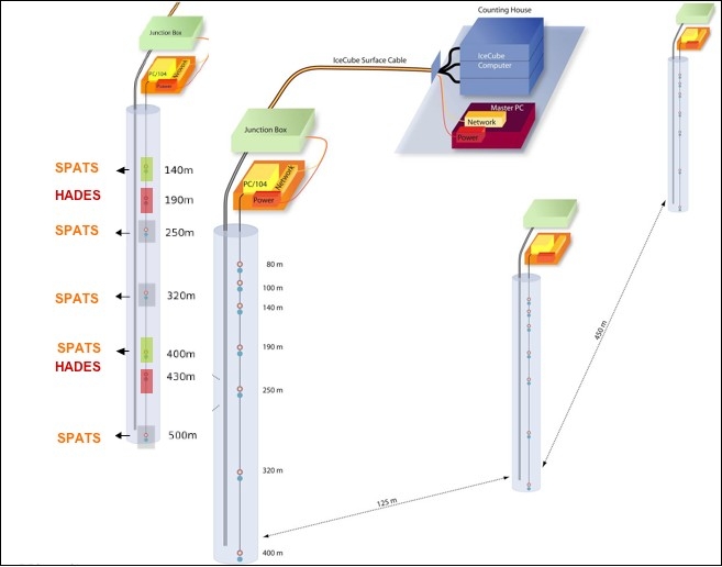
SPATS
: South Pole Acoustic Test Setup
●
RICE
: Radio Ice Cherenkov Experiment
●
AURA
: Askaryan Underice Radio Array
●
NARC
: Neutrino Array Radio Calibration
●
Surface radio antennas
(stand alone)
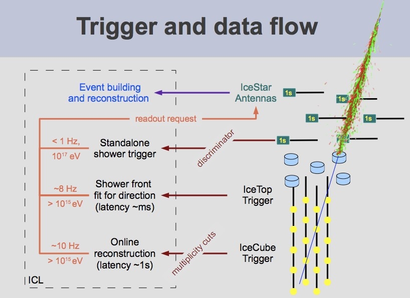
7
Status Acoustics
SPATS
8
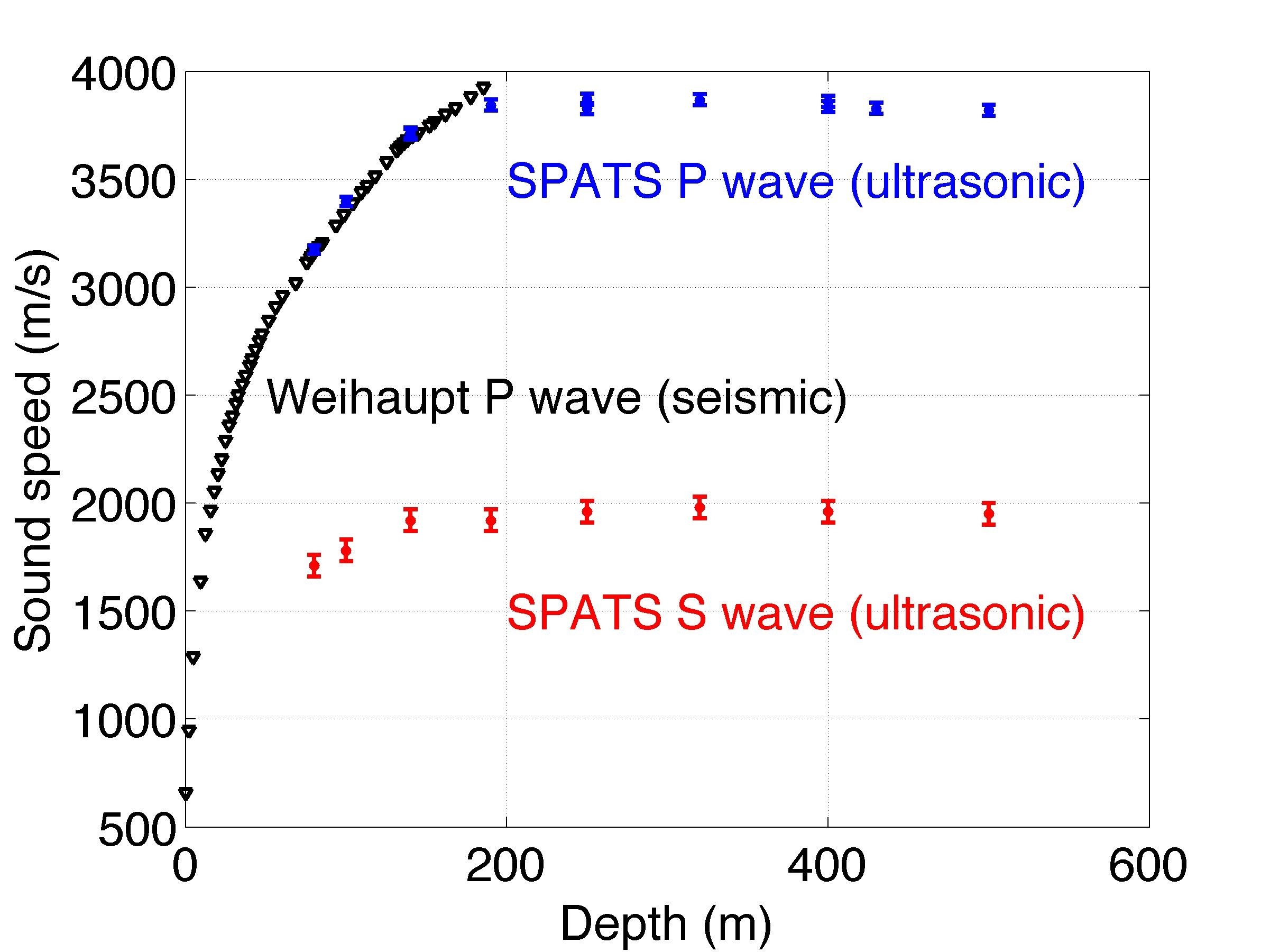
Speed of sound
●
Also shear waves
are relevant!
–
helps with
reconstruction
●
Precision
measurement
ready for journal
publication in
~ weeks
9
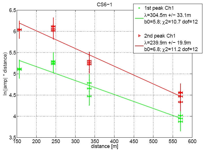
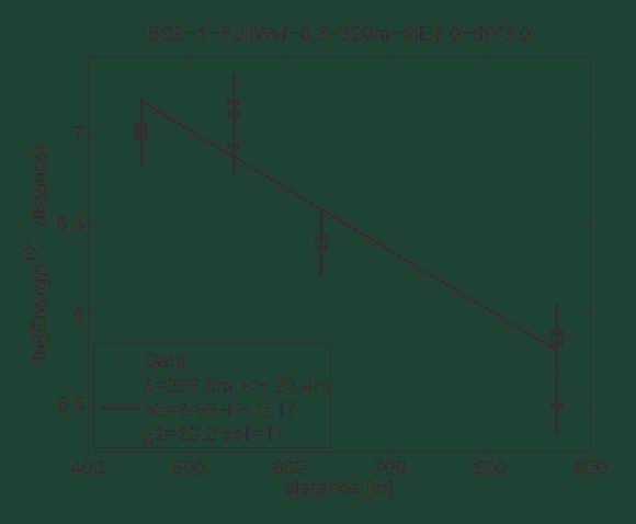
Acoustic attenuation
Amplitude
1
st
/2
nd
peak
Energy
time domain
●
Ball park: 300m ± 100 m
Expectation was kilometers
●
Unclear whether attenuation is short
because of absorption or scattering
10
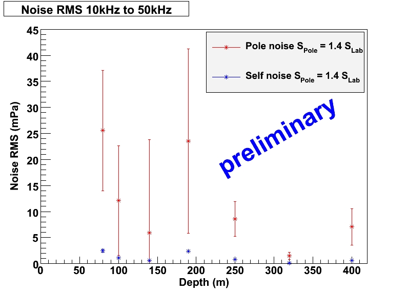
Acoustic noise (DC)
Low continuous noise level
11
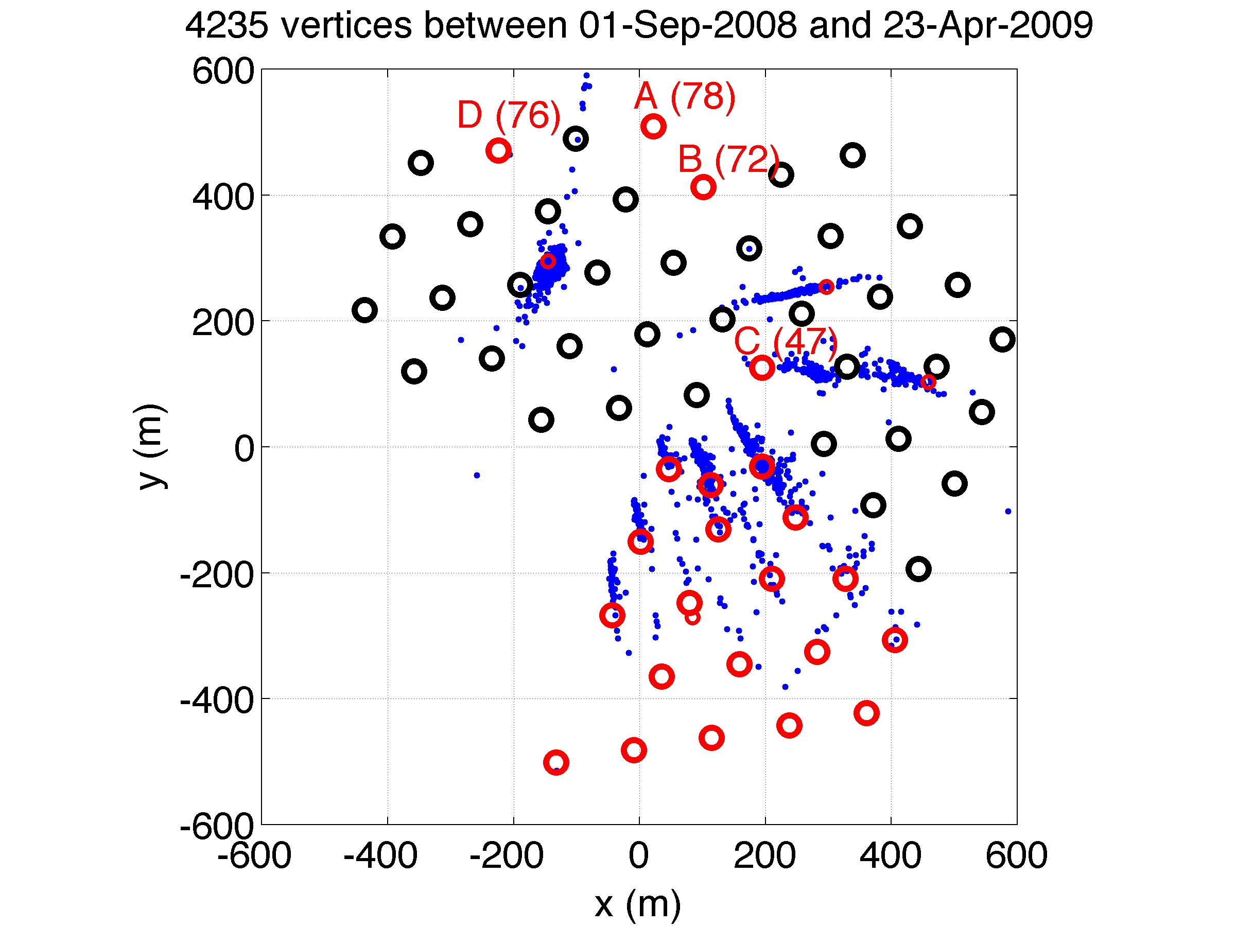
Acoustic noise, transients
●
Transients
correlate with
–
Rod wells for drilling
–
freeze in of IceCube
holes
●
No correlation
found with “dry”
rod well
–
blind analysis proof
12
2
C
a
b
l
e
s
(
S
P
A
S
E
)
125
m
Back to top
SPASE
Back to top
AMANDA DAQ
Building (MAPO)
Back to top
SPASE Building
Back to top
Antennas
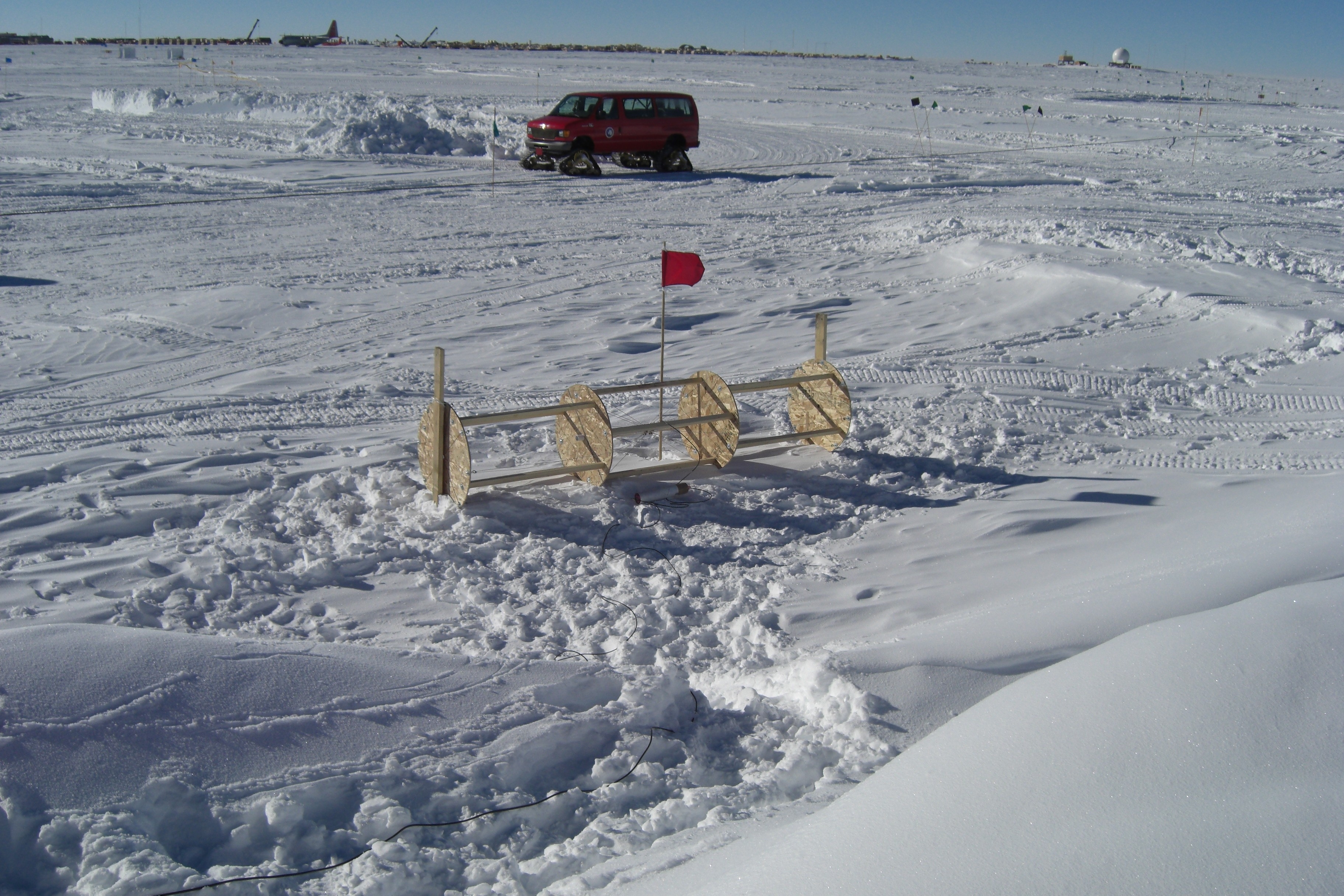
Status air shower radio
Back to top
Test array:
4 antennas
read out with
RICE DAQ
13
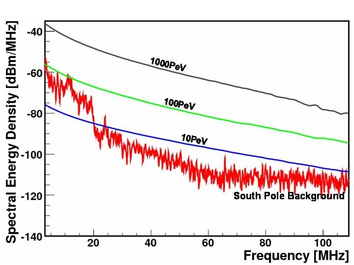
Surface RFI (DC)
Low continuous noise level
14
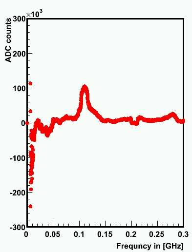
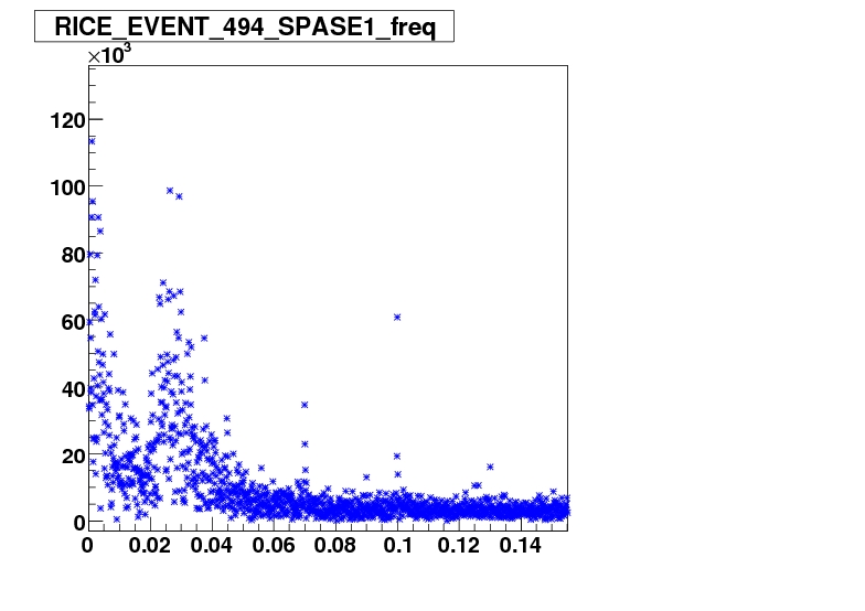
Transient surface RFI
- uncalibrated -
GHz
ns
NoEvent
Event
GHz
0.
1.
0.
1.
2.
2.
RFI
difference
Event - NoEvent
narrow frequency band of RFI emission
compared to broad band air shower signal
RFI
15
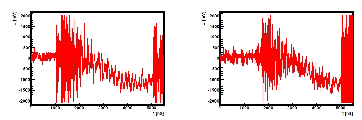
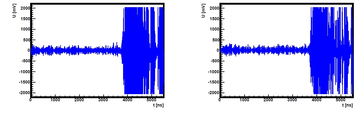
Pinger Data Reconstruction
Pulser Starts
Pulse reaches DAQ
Back to top
MAPO 1
MAPO 2
Back to top
SPASE 1
SPASE 1
16
Pinger Data Reconstruction
Pulser Starts
Pulse reaches DAQ
Back to top
MAPO 1
MAPO 2
Back to top
SPASE 1
SPASE 1
Pre
Back to top
l
imin
a
ry
Back to top
RMS of reconstruction ~ 3 m
17
Shallow (~300m)
Deep (~1400 m)
surface
Back to top
junction
box
Counting
house
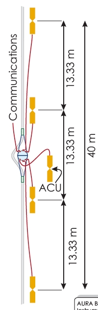
Status in-ice radio
●
AURA cluster:
–
Digital Radio Module (DRM) – similar to DOM
–
4 antennas, 1 Antenna Calibration Unit (ACU)
–
IceCube sphere, DOM main board (waveforms)
●
5 clusters: 2 in 06/07; 3 in 08/09 (with NARC)
●
2 channels (“antennas”) down to 100MHz
●
15/20 channels are working
18
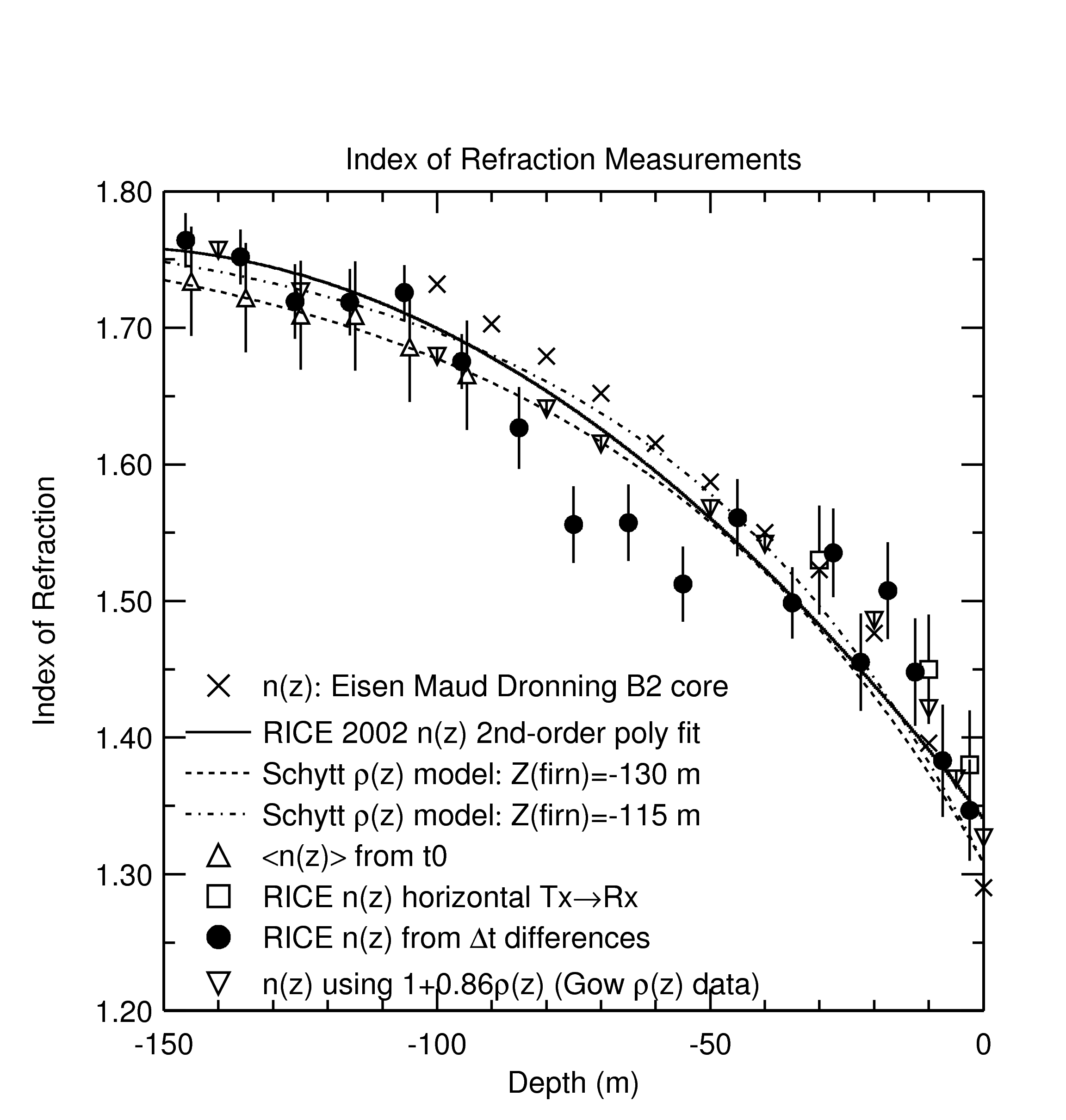
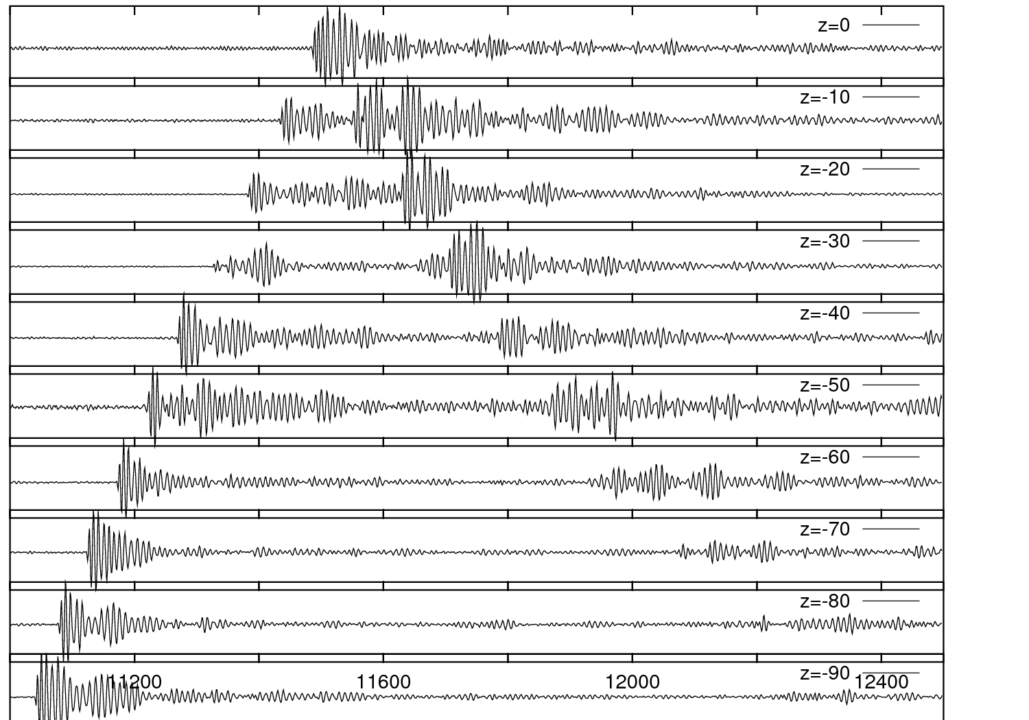
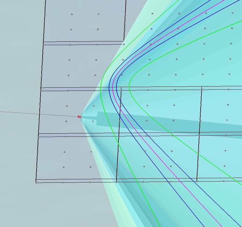
Status in ice radio: Index of refraction
●
Changing index helps to
reduce surface noise
pickup
●
... but shadowing for
shallow deployment
●
No birefringence
19
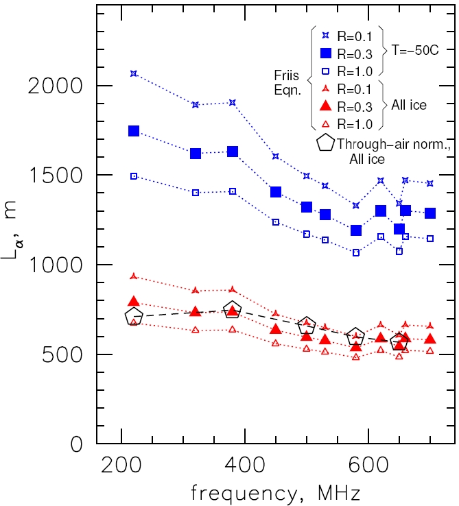
Radio attenuation
temperature region for shallow deployment
R=1.0 : worst case scenario
20
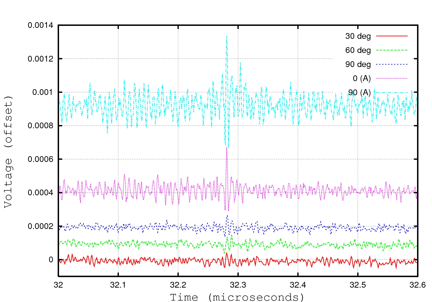
Forced
Trigger
Trigger - details
In ice RFI transients with AURA
Angular resolution:
few degrees
21
Status summary:
Attenuation
●
Mostly known
–
great progress in acoustics with last season
but unfavorable result
–
known from radio reflection of bed rock,
direct on-site measurements would be nice
confirmation
–
Negligible for air shower radio
22
Status summary: “
Refraction
”
●
Refraction, signal speed, depth
dependence:
no evident show stopper but impact
on detector designs
–
good knowledge in acoustics but needs
additional studies for shallow holes
–
in radio uncertainties can still influence
detector design
–
E-field needs further attention to understand
signal strength, B-field configuration wrt veto
coverage of air shower radio.
23
Status summary:
Noise
●
Noise/EMI/background:
significant
uncertainties wrt transients
potential cost driver (electronics)
–
Acoustic: constant level of noise favorable
(compared to sea), most transients
from known
sources
–
In-ice Radio: deserves attention
●
RICE:
–
favorable in winter, challenge in summer
–
transient
background rate O(1/minute) in multiplicity
●
air showers could be (additional) transient
background
–
Air shower radio (on-ice antennas) could be
instrumental to get rid of EMI in-ice ... for itself
looks promising, work in progress.
24
Current implications from site exploration
●
GZK is main science motivation
long attenuation length for radio signals in ice
⇒
Askaryan radio detector in ice main
instrumentation and design driver
●
Pursue integrated approach of air shower radio
detection
together with neutrino detection for
–
additional (EHE) vetoing
→ increased overlap with optical
–
EMI reduction and monitoring
–
air showers may provide test beam for in ice
–
... and of course air shower physics
–
use joint infrastructure
25
Role of acoustics
●
Reevaluation of hybrid option needed in view of
shorter than expected attenuation length
●
Finish site exploration e.g. understand attenuation
mechanism
●
In case optimistic scenario prevails
–
scattering accounts for short attenuation
reduces previously diverging vertical demands
–
shallow co-deployment in narrow holes feasible
–
extra cost reasonably small fraction
...
then
–
Hand full of coincidences that no one else in the
world can do – independent reco + signal
–
Add independent evidence for neutrinos to radio
signals
26
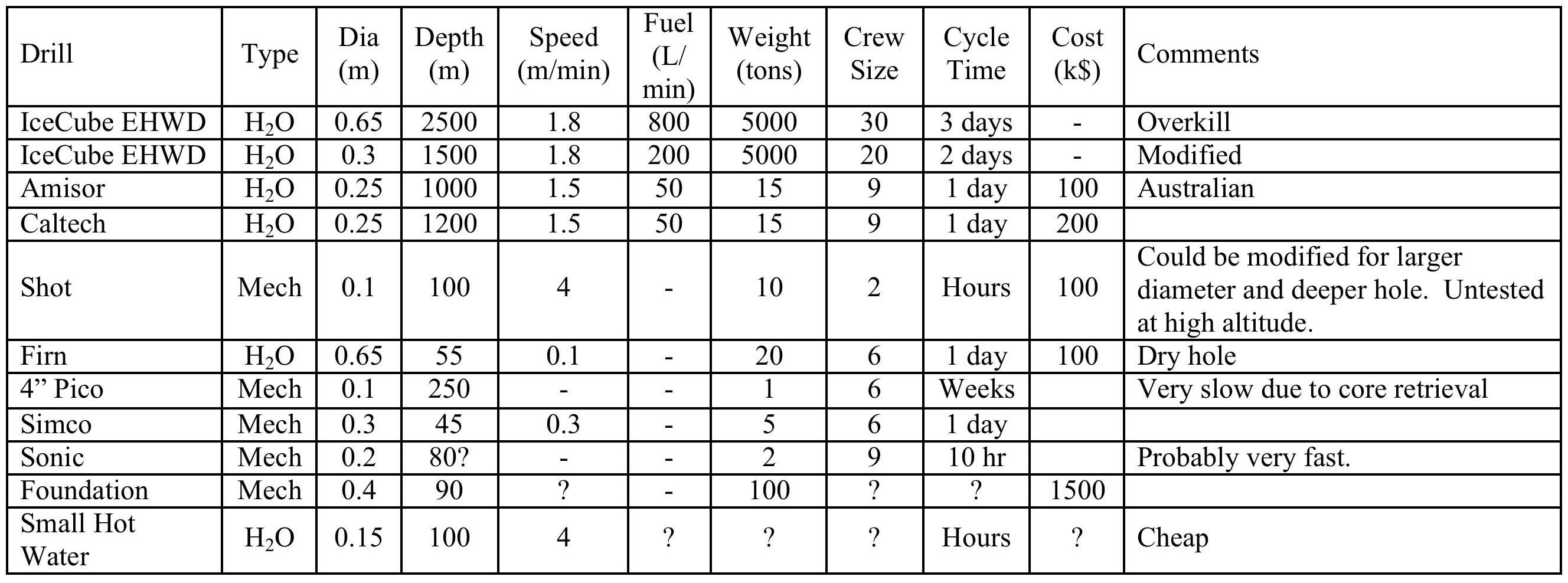
Drill options for large array
Findings from 2 drilling workshops held in Madison 2008
Current line of thoughts:
●
down to
200m
depth
at reasonable cost
●
Dry holes much easier
than wet holes.
27
Road forward
●
Use last holes/seasons for
–
prototype sensor co-deployment
–
tests of digitization strategies
–
instrumentation for further site studies
e.g. retrievable sensors and radio pingers
–
find coincidences of air shower radio with IceTop
●
Aim for dedicated (dry) holes to test
–
Deployment methods
–
Couplings of sensors with holes
●
Assume maximum drilling depth of up to 200m (cost)
–
acoustic scattering might help reduce previously
diverging vertical demands
28
●
Clarify role of non-IceCube members 2009
●
Start „Letter of Intent“ (LOI) at R&D workshop in June and
sign in fall 2009 to demonstrate:
–
serious intent of signing groups (FAs)
–
scientific importance
–
long term time scenario and milestones
●
Finish basic exploration of ice properties (season 09/10)
●
Start extensive MC studies (fall 09)
●
Track down number of different detector options (2010)
●
Write „Proposal“ for submission to FA‘s early 2011
–
expand letter of intent based on MC and hardware studies
–
scalable design plan and 2 phase structure
–
work out realistic budget plan
Near term time line
29
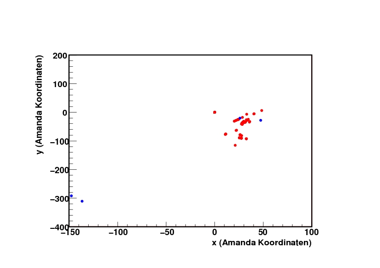
Hole 36, -250 m
Hole 57, -288 m
Immediate future with AURA
●
More RFI studies
●
new stronger transmitter
⇒ first inter-cluster calibration source
30
Radio attenuation: Plans for
direct on-site measurements
AURA
or
AURA
AURA
Options:
2. Frozen-In Tx and Rx
+ good coupling; – fixed position
3. IceCube holes pre-deployment
+ many depths; – water coupling
Previous pinging with RICE
direct signal path
signal path with total reflection
31
●
Ice attenuation (shallow, horizontal)
●
Coincidences with IceCube/IceTop
●
South pole RFI map vs. time
●
Possibly produce limit on GZK neutrinos:
–
Sensitivity calibration
–
Life time
–
Simulation
To-Do list radio
32
●
Attenuation (if scattering) strongly frequency
dependent
–
Test with broadband pinger
–
Confirm attenuation in perpendicular direction
●
No transients below ~300 m
–
No sources? – Unlikely
–
Mechanism quieting deep sources (relevant to radio?)
–
Lower pinger to deeper depths (~1000 m)
●
New set of pinger runs in 2009/2010!
●
Collect data needed to publish ice properties
Season 09/10 plans for acoustic
33
Detector design considerations
●
Sensors:
–
Frequency range and band width
–
Antennas type
●
Geometry:
–
Shadowing effect
→ Deep deployment
–
Ice Temperature
→ Shallow deployment
–
Drilling cost and time
→ Shallow deployment
–
Hole diameter can limit
antenna design
–
Wet/dry hole
Unique signature of Askaryan:
short pulse, linearly polarized
- Capture polarization?
- Low freq has wider signal
cone but more noise
- Narrow holes effect design
dense shallow versus sparse deep
34
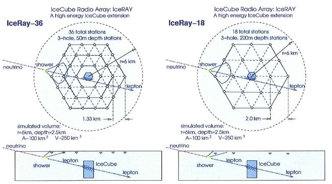
Case study IceRay
– fully digitized waveforms, 50 km
2
–
Comparison: High density, shallow (50 m) versus sparse, deep (200m )
3-9 GZKs per year (“standard flux”), 0.3-2 coincidences with IceCube
⇒ develop plan to scale beyond 100 km
2
by factors
35
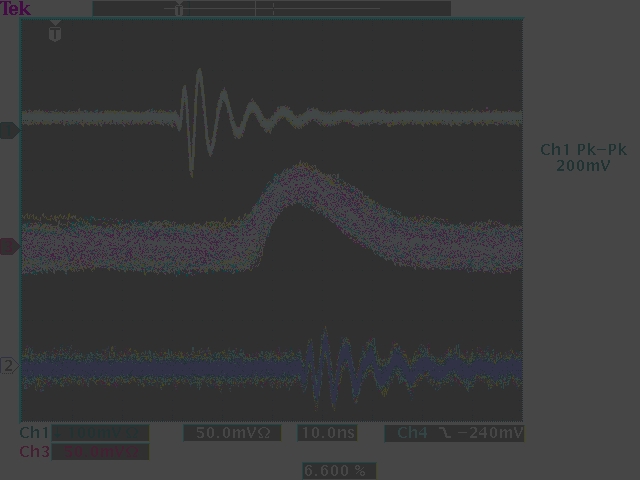
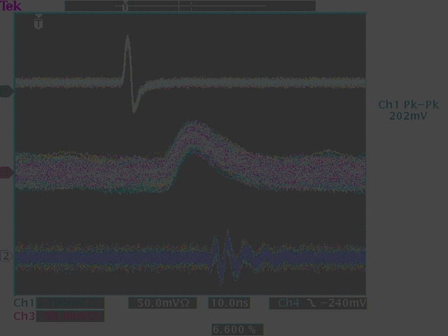
Example for technology choices
Pulse shaping and triggering
versus waveform capture
shaped pulse
AURA
Back to top
waveform
Short Bipolar Pulse
“Antenna-like” Transient
If only envelope gets sent to surface:
●
Digitization speed can be lowered
➔ towards demands of air shower radio and acoustic
●
no interference with several antennas in a hole
➔ use loop through signal cable
Only feasible if RFI is well behaved
36
Data acquisition considerations
fully digitized waveform array
Pros:
+ good timing, full frequency info
+ Method proven by ANITA and RICE
Cons:
– Expensive, more complicated units
– power consumption
Challenges:
Handling large amount of data
Back to top
Pulse shaping & envelope trigger
Pros:
+ cheaper units → large array
+ Simpler detector
Cons:
– Limited information
Challenges:
information sufficient to reject
background and detect GZKs ?
37
Look-back buffer read-out for
detector components (here surface)
38
Sensor String Configuration (here: in ice radio)
CM Chokes
(Sets Dipole length)
“Bottle Brush”
Clip-on Antenna Elements
(Allows Reel Deployment)
TDA Node 1
TDA Node 2
“Common Mode” TDA
Node:
- Signal Cable Shield = Antenna Element
- Envelope BW minimizes crosstalk
- Multi-sensors on one cable possible
- Azimuthal asymmetry is avoided
~1” diameter bump in cable
~500 mW power consumption
Hole
RF IN
ENV.
OUT
Gain
Envelope
Circuit
PWR
TDA OUTPUTS
Multi-Pair Cable
TDA Rev2
39
Technology choices
●
DAQ and triggering strategy
–
pulse shaping versus waveforms
–
simple local threshold versus local clusters
with phased array type of trigger
●
Energy distribution
–
centralized with cables
–
local with solar panels, wind, peltier effect
●
Signal propagation to central hub
–
cable versus wifi (Auger style)
●
Surface antennas in self trigger mode
versus trigger from IceTop and in ice radio
40
Conclusions & Outlook
●
Site exploration
–
very prolific (several publications in pipeline)
–
Short attenuation length in acoustics
→ Askaryan radio primary driver
–
Hybrid option being reevaluated
●
Upcoming seasons to clarify
–
deployment options (depth, dry/wet)
–
choice of pulse shaping, trigger, digitization
●
Institutional responsibilities to be worked
out at upcoming R&D meeting
●
... head out to extend IceCube and IceTop
by factors at the EHE frontier
41
Thank you!
42
Backup
●
Backup
43
Use IceCube’s resources: holes, comm. and power
• Each Cluster contains:
–
Digital Radio Module (DRM) – Electronics
–
4 Antennas
–
1 Antenna Calibration Unit (ACU)
●
Signal conditioning and amplification happen
at the front end
●
Signal is digitized and triggers formed in DRM
●
A cluster uses standard IceCube sphere, DOM
main board and surface cable lines.
surface
Back to top
junction
box
Back to top
Counting
house
AURA Radio Cluster
A
skaryan Under ice Radio A
rray
44
AURA Radio Cluster
What’s new in the last season
●
An array of 5 clusters:
2 clusters 2006-2007
+3 clusters 2008-2009
(part of the of the NARC initiative)
●
2 channels (“antennas”) down to 100MHz
●
15/20 channels are working
●
Stronger and/or more sophisticated in ice
pulsers (support CW and pulses)
●
IceCube-like DAQ (based on pdaq)
●
Strong surface pulser
Shallow (~300m)
Deep (~1400 m)
45
From Utrecht premeeting
Possible near term timeline:2008-2009-2010
-
Working group and collaboration building -> in progress
-
Write „Letter of Intent“ and sign in spring 2009 to demonstrate:
serious intention of signing groups to in- and out-side world (FA)
scientific importance in comparison to other topics
expected improvement to previous experiments
time scenario and milestones (Hawaii, identify man power)
- Finish basic exploration of ice properties (existing hardware, new deploy?)
-
Agree on deployment scheme already here (?)
-
Start extensive MC studies of different detector options (using above)
-
Start sensor and electronic prototyping
-
Track down number of different detector options based on above
results (earlier?)
- Write „Proposal“ for submission to FA‘s end 2010 (realistic ?)
expand letter of intent to give detailed information
based on extensive MC and hardware studies
still goes with flexible design plan and 2 phase structure
works out realistic budget plan
46
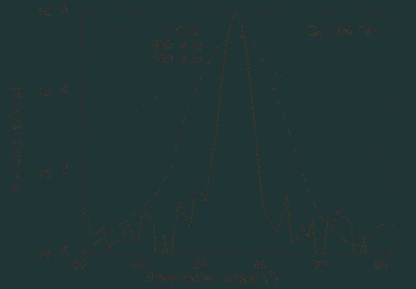
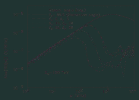
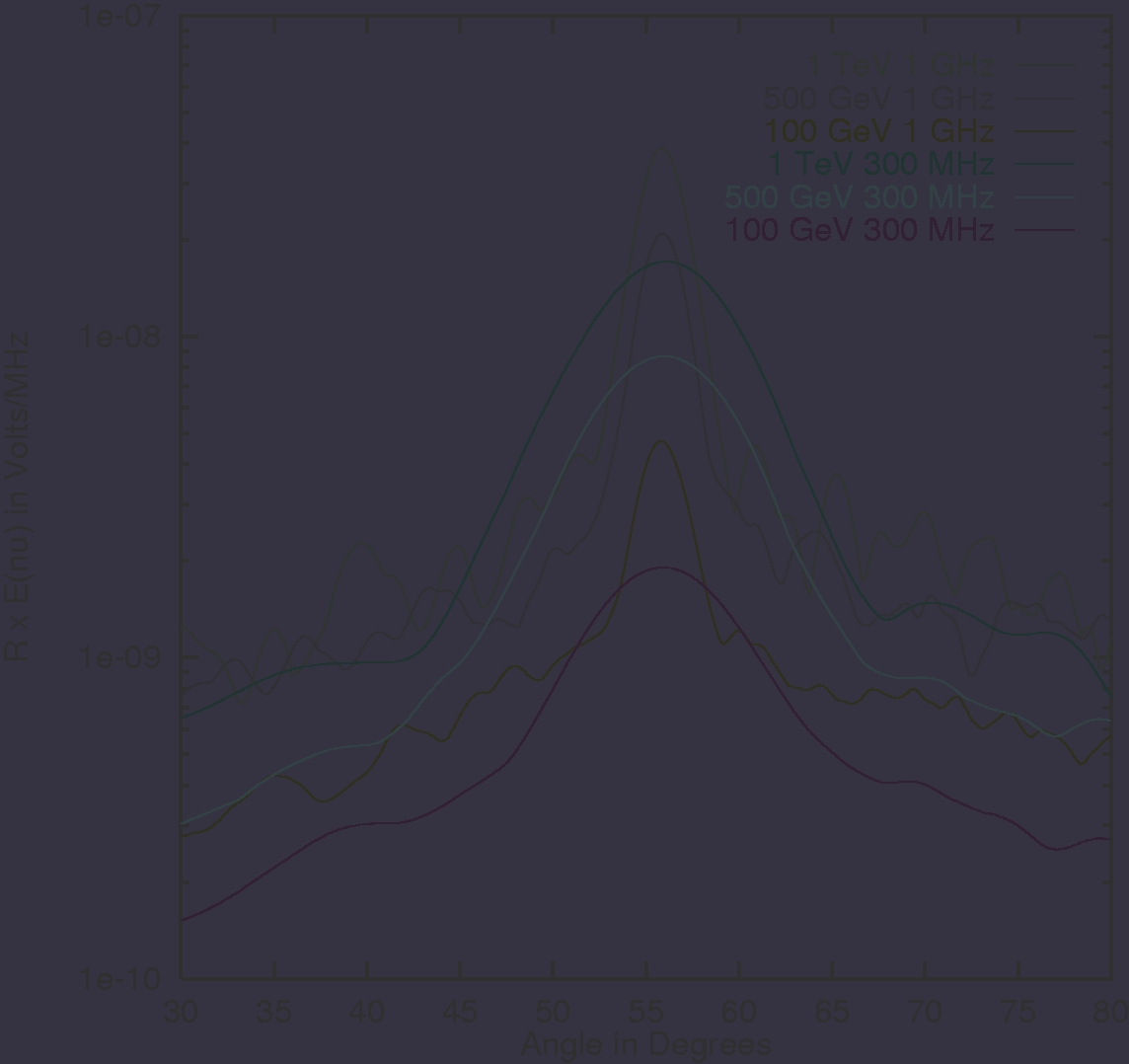
Askaryan Signal
Cherenkov angle=55.8
o
Electric Field angular distributionElectric Field frequency spectrum
A
s
t
r
o
-
ph
/
9
9
0
1
2
7
8
A
l
v
a
r
e
z
-
M
un
i
z,
V
a
z
qu
e
z,
Z
a
s
1
9
9
9
47
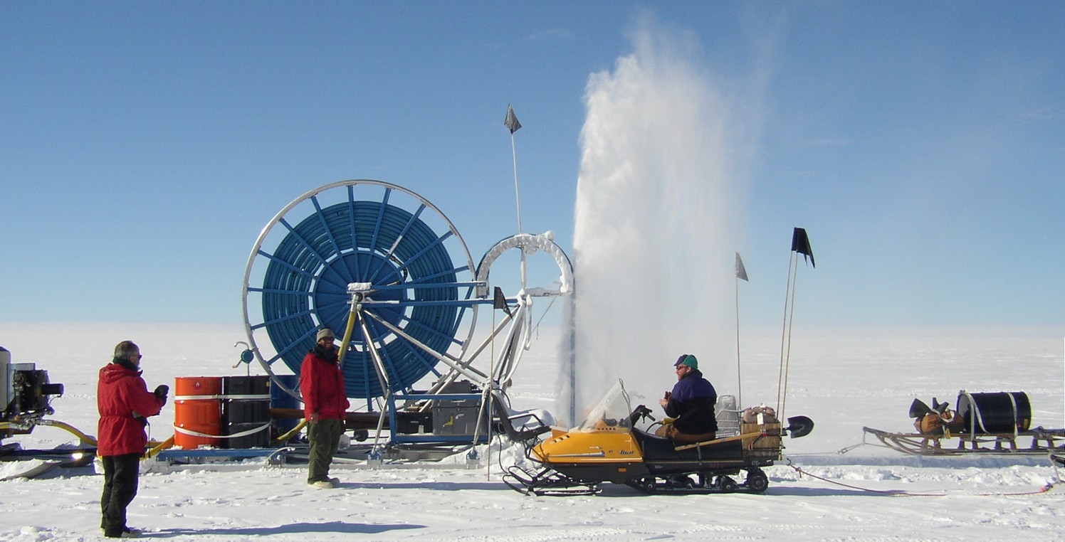
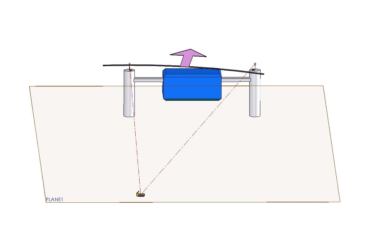
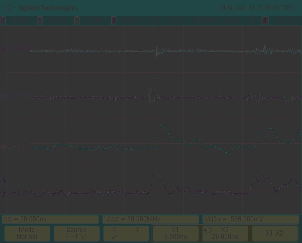
Example Transient
(from snowmobile ignition)
Ignition noise transients from idling snowmobile
Snowmobile was approximately 100m distance from ICL.
Snowmobile was perpendicular with West tower.
Signals as acquired by ic-scope-ag1
Time Delay=20ns W-E, consistent with Angle-of-Arrival (AOA)
Back to top
Transient
Back to top
Wavefront
Back to top
Snowmobile
(transient source)
West
Back to top
tower
East
Back to top
tower
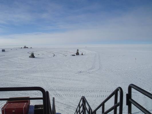
View of snowmobile
from ICL Door
Delta t =20ns
48
Transient sensor array
Kael Hanson
Perry Sandstorm
Many “simple” sensors to provide a snap shot of an Askaryan pulse.
Wide dynamic range, low power, simple output
49
Case study: Transient Detector Footprints
500m x 500m
sensor
20 km
spacing shown
2
0
k
m
“Kilocube”
100km
2
IceCube
IceRay
18,36
“Kilocube”
# of Sensors vs. Density:
333
1000
1200
333
333
3600
500
500
1600
1000
1000
400
Total # of
Back to top
Sensors
Y
Spacing
(meters)
X
Spacing
(meters)
50
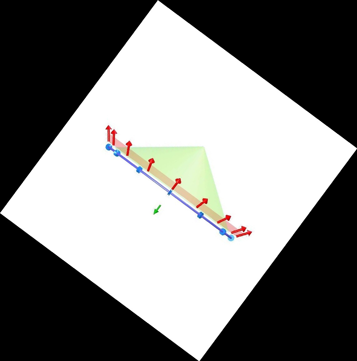
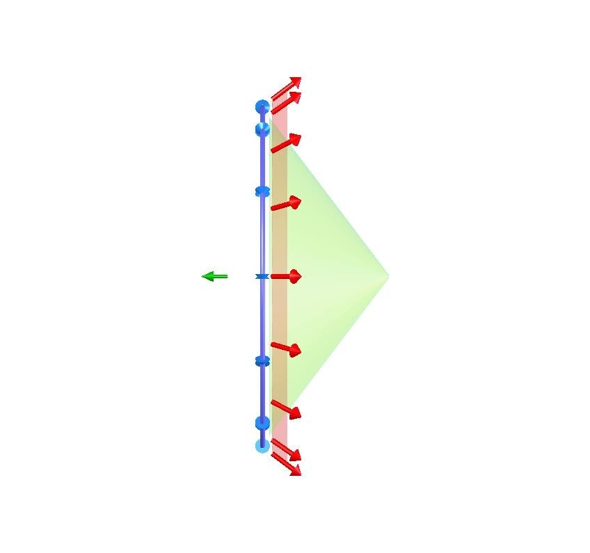
Downward Rejection
via Priority, Coincidence
Real-Time, Simplest “Elevation Gating”
Back to top
TDA (A)
Back to top
TDA (B)
A
B
A
B
A
B
d
~40m
Lowest Detectable
Neutrino
Trajectory
(93 degree zenith)
Surface
Transients
Back to top
Reject
Back to top
Accept
Back to top
Accept
Time Difference Of Arrival (TDOA)
Highest Detectable
Neutrino Trajectory
(36 degree zenith)
Surface Processor
51
SATRA Functional Blocks
(Sensor Array for Transient Radio
Astrophysics)
52
Radio Transient Sensor Instrumentation
Baseline Configuration
~150m
Surface
Firn
Ice
~190m
Active Antennas
with Envelope
Back to top
Outputs
Back to top
(TDAs)
Back to top
Surface
Processor
Assembly
(SPA)
4” Dry
10MHz Clock
Data (RS485)
Slow Ctrl
Back to top
SPA of
Next Hole
1
2
Row
DAQ
Back to top
Envelopes
sent to
Back to top
surface
TDOA =
T
ime-
D
ifference-
O
f-
A
rrival
TOT =
T
ime-
O
ver-
T
hreshold
Elevation ≈
TDOA
Between TDAs (z)
Azimuth ≈
TDOA
Between Holes (d)
Amplitude ≈
TOT
of Envelopes
?
Elevation is determined in real time for each hit at each hole.
?
Azimuth and event signature uses elevation and amplitude
data from all holes hit.
?
Its all in the timing.
“z”
“d”
53
Sensor Array System-Level R&D
●
Source modeling
●
Nominal array sizes needed for event detection and/or limits
●
Array geometry optimization
–
Vertical, Horizontal spacing
–
Number of sensors per string
–
Size of Array
●
Sensitivity Analysis
–
Antenna bandwidth
–
Envelope/discriminator bandwidth
–
Noise; KT, RFI, CR
●
Optimized data format for transmission, filtering, storage
●
Event simulation and filtering
●
Data processing requirements for online filtering
●
DAQ for each row and combiner from all row-DAQs
54
Example data from each hole
Course Time
Back to top
From
Back to top
Masterclock
LSB= 10ns
Range=100us
Back to top
Fine Times
Back to top
From Time-Digital-Converter
(TDC)
Back to top
LSB=250ps
Range=500ns
8bits
14bits
14bits
8bits
Back to top
Hole
Back to top
Address
TDA1
Rise
Back to top
TDA1
TOT
Back to top
TDA2
Rise
Back to top
TDA2
TOT
14bits
8bits
TDA 3,4, etc
Compare TOT
(amplitudes)
for
“hit quality”
Compare TOAs for
Elevation Angle
55
Sensor String Baseline Configuration
CM Chokes
(Sets Dipole length)
“Bottle Brush”
Clip-on Antenna Elements
(Allows Reel Deployment)
TDA Node 1
TDA Node 2
“Common Mode” TDA
Node:
- Signal Cable Shield = Antenna Element
- Envelope BW minimizes crosstalk
- Multi-sensors on one cable possible
- Azimuthal asymmetry is avoided
~1” diameter bump in cable
~500 mW power consumption
Hole
RF IN
ENV.
OUT
Gain
Envelope
Circuit
PWR
TDA OUTPUTS
Multi-Pair Cable
TDA Rev2
56
Sensor String Development
separable activities/disciplines by color
●
TDA PCB
–
Circuit topology
–
Parts selection
–
Schematic Capture
–
PCB layout, potting, mechanical attachment
–
Spice optimization of antenna match
●
Common Mode Antenna
–
XFTD modeling of elevation response
–
NEC modeling of elevation response
●
Cable
–
Spice or Qucs simulation of envelope transmission
–
String fabrication and deployment
57
SPA
(Ele
B
vat
a
ion
s
b
e
y h
l
i
i
-r
n
es
e
TDO
C
A,
o
Am
n
pli
f
tu
i
d
g
e
u
by
r
TO
a
T)
tion
Discriminator
Discriminator
Envelope
Back to top
Signals
Back to top
Upper
TDA
Back to top
Lower
TDA
Threshold
START
STOP CH1
STOP CH2
TOT
Time-Digital
Converter (TDC)
4-fold stops/ch
65ps bin size
Min 200ns window
ALU
Hit Processor
Hit Buffer
Elevation
& Coinc.
Fine Time
Data
Back to top
Coarse Time
(x10) Master clock
TDC
Back to top
Settings
Back to top
Buffered Hit Data
Back to top
Serializer
Get Data
Back to top
Master Clock Pair
Back to top
Data Pair
Back to top
Slow Control
Pair
TDOA
Back to top
Adjacent
SPAs
58
SPA Development
separable activities/disciplines by color
•
Surface Cable and Interface
•
Discriminator
•
TDC (or simple elevation gate for ’09-’10
expmt)
•
Hit Processor (µProcessor or FPGA)
•
PLL & Course-Time Counter
•
Data Format and Buffer
•
DC-DC Converter/ Head-end PSU requirements
●
Enclosure and Integration
59
SATRA South Pole Testing
●
Proof of Concept for Envelope Detection
’08-’09 (done)
–
Goals:
Show feasibility of TDOA technique for background rejection using envelope signals from TDA
–
Setup:
Two TDAs connected to Horizontally-separated antennas on ICL Towers.
–
Enables:
Continued transient background monitoring with programmable oscilloscopes
●
Real-time elevation gating with vertically-separated TDAs
’09-’10
–
Goals:
Background Rate vs. (elevation & threshold)
–
Setup:
single test string in multiple IceCube firn and/or rod well holes, simplified SPA. Measure
sensitivity to surface and AURA transmitters
–
Enables:
comparison of candidate TDA / antenna configurations, verification of envelope discriminator
and basic elevation gating.
●
Small test array (3km x 1km); (~10x3 holes)
’11-’12
–
Goal:
(Rate & amplitude) vs (elevation & azimuth & threshold) DAQ verification
–
Setup:
Upgraded RAM Drill, 30 strings, 30 full-function SPAs, 30 surface links, 3 “Row” DAQs
–
Enables
: Verification of TDC and course timing circuitry, Optimization of SPA comms, initial sensitivity
calibration. Optimization of RAM drill. DAQ and filter testing, Optimize TDA-TDA and Hole-Hole spacing
●
Large test array (3km x 2km); (~10x6 holes) ’
12-’13
–
Goals:
Verify changes to RAM drill and Instrumentation; grid spacing should conform to final geometry
–
Apparatus:
Upgraded RAM drills, 60 strings, 60SPAs, 60 surface links, 6 Row DAQs
–
Enables:
verification of configurations and procedures for large-scale drilling and deployment, Establish
Flux Limits and possible event detection.
●
SATRA KiloCube (20km x 20km); (400-1600 holes)
‘13-’16
–
Goals:
Detect significant number of GZK events
–
Apparatus:
$15-20M
–
Enables:
Event detection and confirmation by spatiotemporal signature.
60
Envelope / TDA Proof-of-Concept Testing
South-Pole 08-09
Ignition noise transients from idling snowmobile
Snowmobile was approximately 100m distance from ICL.
Snowmobile was perpendicular with West tower.
Signals as acquired by ic-scope-ag1
Time Delay=20ns W-E, consistent with Angle-of-Arrival (AOA)
Transient
Back to top
Wavefront
Back to top
Snowmobile
(transient source)
West
Back to top
tower
East
Back to top
tower
View of snowmobile
from ICL Door
Delta t =20ns
61
Sensor experiment for ’09-’10
Rate vs. (Threshold, Elevation)
●
Goals:
–
Test Common-Mode antenna/TDA design
–
Optimize envelope/discriminator parameters for rejection of
background transients by virtue of their elevation
–
Get low-threshold data regarding SP background transients
●
Basic vertical string with two Rev2 TDAs
–
Temporary, self-contained apparatus (e.g. battery powered)
–
Can be moved from hole-hole (e.g. IC firn holes before drilling)
●
Simplified Surface Processor (SPA)
–
Acquires background rates vs. (threshold, elevation)
–
Simplified design allows low thresholds with ~MHz hit rates
–
Threshold scan is repeated at each elevation increment.
–
Complete threshold/elevation scan should take a few hours.
62
Simplified SPA -Elevation Scan for ’09-’10
Disc-A
Back to top
Disc-B
Back to top
T= 200ns (Max TDOA for z= 40m)
Back to top
Variable delay
Back to top
of PW-A
Back to top
AND Output
Back to top
PW-A = PW-B
Variable Delay Range≈ “elevation range”
Mono ~10ns
Mono ~10ns
Variable Delay
Mono 100ns
Elevation
Setting
Rate
Output
0
Threshold
Setting
2
1
3
4
Back to top
Rate Output
1
2
3
4
5
5
A
B
Back to top
Envelope
s
From
Hole
40m
Resolution
Setting
Pulse width≈ “elevation resolution”
TDOA
63
Askaryan pulses from air
shower core